AND
Category: Gate Tier: Basic
Purpose
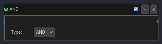
The AND gate outputs a positive pulse only when ALL connected input sensors are active simultaneously.
Visual Reference
Runtime Behavior
Inputs
Input 1 (Boolean): First input signal
Input 2 (Boolean): Second input signal
Input 3 (Boolean): Third input signal (optional)
Input 4 (Boolean): Fourth input signal (optional)
Outputs
Output (Boolean): True only when all inputs are true
Properties
gate_type (option, “AND”): Logic gate type (can switch between AND/OR/XOR/NAND/NOR without reconnecting)
Execution Behavior
Tick Behavior
Evaluate all connected inputs
Output is true only if ALL inputs are true
Generate positive pulse on rising edge (false->true)
Generate negative pulse on falling edge (true->false)
For invert behavior, use NAND gate instead
State Changes
State becomes ACTIVE when all inputs are true
State becomes INACTIVE when any input is false
State transitions trigger appropriate pulses
Edge Detection
Positive pulse: When output transitions from false to true
Negative pulse: When output transitions from true to false
Examples
Basic Usage Connect two sensors (e.g., Keyboard + Mouse) to AND gate inputs. Output activates only when both sensors are active.
Advanced Usage Use with 4 inputs for complex multi-condition logic. Enable Invert for NAND behavior.
Properties
Property |
Type |
Default |
Notes |
|---|---|---|---|
Type |
option |
AND |
Logic gate type - change without reconnecting |